What is sheet metal stamping process?
A sheet metal stamping process is a metalworking process carried out at room temperature wherein parts are both cut and shaped from a parent metal strip or coil by feeding them into several dedicated dies securely mounted on stamping presses that apply intense pressure.
- The Parent material is metal in the form of either strips previously cut from sheets or coils slit from wider coils. However, non-flat metal products like pipes, tubes, aluminium extruded profiles and mild steel angles/channels are also stamped.
- It is carried out at room temperatures, that is, it’s a cold working process.
- Part-specific Dies, usually in numbers ranging from three to six, are used-.
- Stamping presses exert enormous pressure to impart desired shape features to the parts.
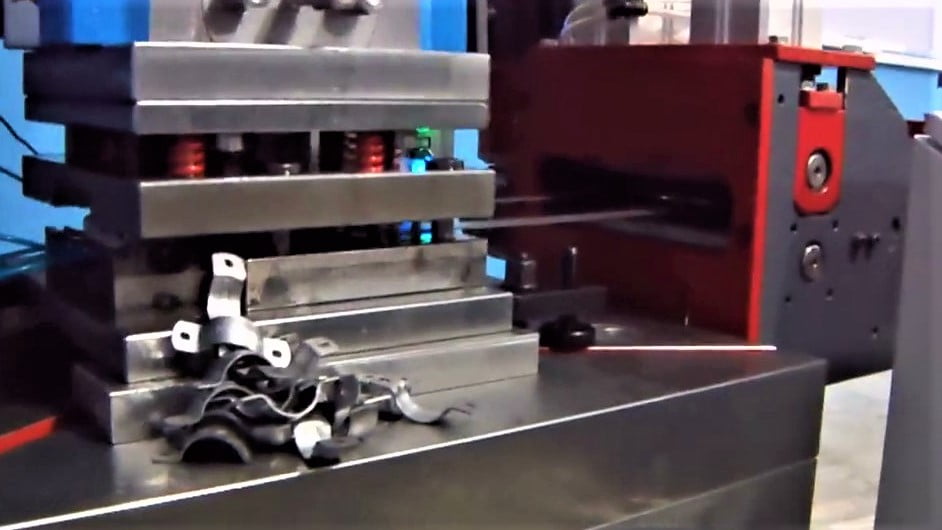
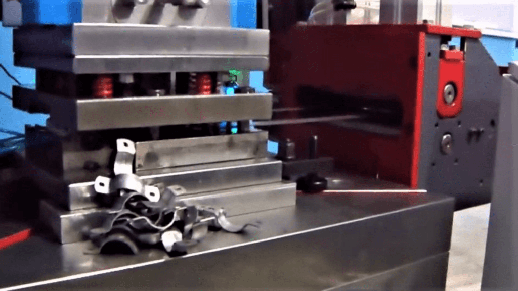
Sheet metal stamping process for saddles using a progressive die and coil feeder
Parts thus made are called stampings in some parts of the world. In some other parts, they are known as pressed parts or pressed components. Likewise, the sheet metal stamping process is variously known as metal stamping, stamping manufacturing, and sheet metal pressing.
What products are made from the sheet metal stamping process?
It’s impossible to not find any stamping around!
Hardly an article in the kitchen cannot owe its existence to the sheet metal stamping process. Pots, pans, spoons, knives, forks, can openers, and cookware are made using the metal stamping process.
It’s because of the stamping process that the average person can afford an automobile. Sheet metal stamping is used to make the doors, hood, trunk, roof, gas tank, windshield wipers, license plate, and hundreds of internal car parts.
Almost all of the refrigerator’s components are stampings. The same holds true, to a large extent, with washing machines, too.
Look around any room, and you’ll find most of the parts in the lighting fixtures; the threaded portion of light bulbs; radiator covers; the computer case; the structural frame of audio systems, LED TVs, computer printers, and Xerox machines; they are all stamped parts.
The end covers you see on electrical motors, the stator core, and the armature all make use of stampings. The enclosure for electrical switchgear and various electrical contacts is made of stampings.
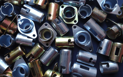
An assortment of automotive bulb holders
Automotive turn signal bulb holder assemblies
Most of the parts of the watch on your wrist are stampings. The eyelets on your shoes, through which laces pass; the eyeglass frame; the shiny metal part in the front of your USB drive; the clip on your ballpoint pen; the stainless steel hooks on your pants; and the car key in your pocket; all these are stampings.
The manufacture of stamped metal components is largely responsible for our current way of living.
Where are stampings used?
Notable industries that use stamping in huge volumes are the Automotive Industry, Electrical Industry, Aerospace Industry, White Goods Industry, Agriculture Industry, Computer Hardware Industry, Medical Equipment Industry, Utensils and Cookware Industry, and Defense Equipment Manufacturing Industry.
The automotive industry is, by far, the biggest user of sheet metal stamping. In fact, a vast majority of innovations in stamping technology have come from the automotive industry.
Why stamping?
It’s not for nothing that the metal stamping process has become the workhorse of the manufacturing industry. For one, the stamping process, even without automation, is much faster than other competing metalworking processes like machining, casting, fabrication, and extrusion. Another bright point in favor of stamping is that it’s capable of being highly automated compared to competing processes. Yet another advantage is that it’s capable of delivering stampings to exact specifications.
All this translates into:
- very high production volumes
- all parts meeting the exact specifications in a repeatable fashion
- much lower process cost per part
Metal stamping is used because it can meet high production volume requirements, exact specifications, and lower cost targets.
What are the various steps in stamping?
Almost always, there are multiple steps involved in the production of parts through the stamping process. A notable exception is the stamping process using progressive dies, wherein multiple processes are carried out in a single die with one stroke of the stamping press.
When multiple steps are called for, blanking is invariably the very first step. Flat pieces, called blanks, are cut from the parent material using a dedicated blanking die. The parent material is in the form of strips or narrow-width coils. Blanks are more manageable than strips or coils due to their smaller size.
From here on, the sequence of steps can be different depending on the part geometry and its dimensional tolerance requirements.
- If the stamped part is a simple plain washer with an outer diameter and a hole in the center, the next step would be a piercing process.
- If the part is a shallow dish with a hole in the bottom, the next two steps would be forming and piercing.
- If the part is bent at some angle, the next step would be bending.
- If the part is a deep container (also known as a shell or a cup) with a hole in the bottom, the next sequence would be several drawing operations (depending upon shell height to diameter ratio), followed by piercing and lastly, trimming.
- If the part has a single or several raised areas (dimples), the next process would be embossing, which falls under the category called forming.
It is evident that the number of steps as well as the sequence in which they must be performed vary from part to part. Therefore, no universal rule can be laid down.
What are the various types of stamping processes?
Different authorities on the subject have different views as regards the various types of stamping processes.
Looked from the perspective of the manner in which a workpiece is handled during the complete sequence of operations , the stamping processes are classified as:
- Conventional Stamping
- Progressive Die Stamping
- Transfer Die Stamping
- Four-slide Stamping
Let’s dig a bit deeper into each of these four processes.
Conventional Stamping Process
In the conventional stamping process, the workpiece is transferred manually or mechanically from one press to another in order to accomplish various stamping operations. They may not necessarily occur at the same time in an uninterrupted, continuous fashion. If a part requires three stamping operations, each requiring a 100-ton press to accomplish them, and if the press shop has only one such press, the process cannot be carried out concurrently and continuously. This type of process is invariably associated with a marked increase in work-in-process inventory. Several presses and several dies are required.
Progressive Die Stamping
Progressive die stamping is a process in which a single, complex, and usually very expensive high-precision die is employed to produce one or more finished parts (not always, but in most cases) with each stroke of the press. Contained within the progressive die are several ‘stations’, each performing one of the operations warranted by the part with each stroke of the press. All required operations occur concurrently and continuously. Obviously, there are interruptions whenever coils are loaded onto the decoiling equipment. But from the start to finish of each coil, the process is concurrent and continuous. A much higher tonnage press with a larger bolster area is required as tonnage and space requirements are obviously higher.
Transfer Die Stamping
Transfer Die Stamping is a process in which as many presses as warranted by the part are laid out strategically on the shop floor and parts are ‘transferred’ from the previous press to the next using an automated mechanical transport system. The presses and the transport system are synchronized. As a result, a finished part per cycle is obtained in an uninterrupted, continuous fashion. This process offers distinct advantages in the production of large parts.
Four-slide Stamping
Four-Slide Stamping has four rams (slides) mounted strategically on the machine, and they move sequentially in straight lines, each performing its assigned stamping operation precisely at the time governed by the sequence. The sequence timing is adjusted by adjusting the positions of the cams. It’s a high-speed process but the downside is it’s suitable for only narrow-width parts such as various types of clips and clamps. Another limitation is that the process cannot produce drawn parts like cups and containers. The process is versatile in the sense that it can produce parts with several complex bends at a fast rate and rather inexpensively. Four-slide machines can have more than four slides. Parts are made from narrow-width coils.
Looked from the perspective of how a part is altered in its 3-D geometry, stamping processes can be classified as:
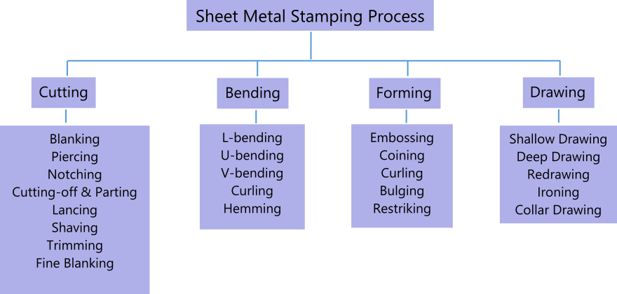
Cutting Operations
In sheet metal stamping, cutting is an outcome of a shear failure of the metal in question. A pair of scissors cutting a sheet of paper is a quintessential example of shear failure. Another very common example is that of punching holes in a sheet of paper with a punching machine as shown below.
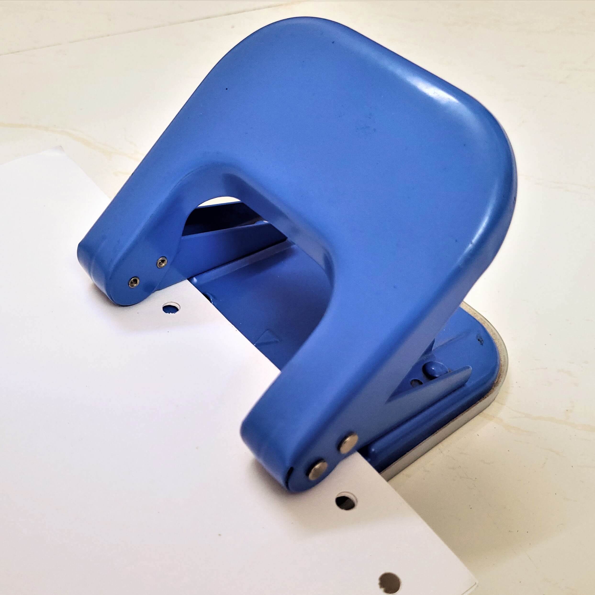
Paper punching machine Photo credit: Reena Shah
Shear failure occurs when an applied force exceeds the shear strength of the material. The shear strength is a measure of a material’s resistance to sliding of its internal structure past each other under the applied force.
Just as a sheet of paper is cut between the edges of two metal blades moving relative to each other, in the same way a punch moves past a stationary die and shears the piece of metal resting on the die face. Internal structure of the stock material at the cutting line slides past that of the detached material due to the intense pressure of the punch.
The following figure shows what happens in cutting due to shear failure of the material.
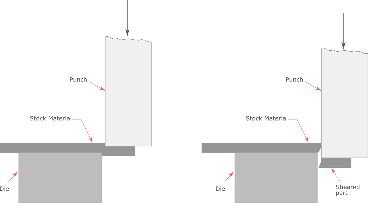
All cutting operations in the metal stamping process are fundamentally the same in the sense that they all cut material by shearing.
Sheet metal cutting operations are further divided into:
- Blanking
- Piercing
- Notching
- Cutting off and Parting
- Lancing
- Shaving
- Trimming
- Fine Blanking
Each of these operations is briefly touched upon in the following paragraphs.
Blanking
Almost always, blanking is the first process a stamped part undergoes, the intention being to separate the flat component from the unwieldy stock material (coil, sheet or strip).
Blank geometries can be as simple as circles and polygons. They can be very complex also.
The following example of a key is a moderately complex combination of different geometries. The key blanks are cut from the stock strip so the outer geometric outline conforms to the drawing specifications. This is the first operation, subsequent to which other stamping operations, such as piercing, are performed.

As parts are blanked one after the other, the scrap stock strip is left behind. Because the part cost also depends on how judiciously the material is utilized at this stage, laying out the strip is of paramount importance. Therefore, considerable effort should be spent on exploring several alternative strip layouts before embarking on building a blanking die.

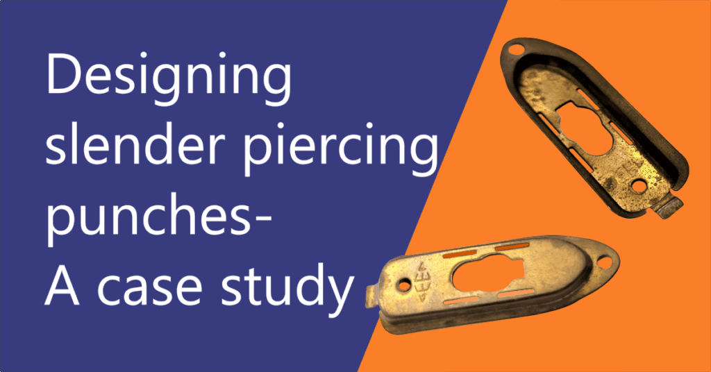
Piercing
Many stamped parts require holes, cutouts, and openings for functional (sometimes for aesthetic) purposes. The operation that cuts material from blanks to produce such holes is known as piercing.
The holes can be geometric or irregular in shape. The circular hole in the key serves a purpose. Round holes are preferred because round punches that are required to make them are inexpensive and the corresponding hole (opening) in the die is less expensive to cut using the wire EDM (electro-discharge machining) process.

The figure on the left shows the key blank after having gone through the piercing process. The material so removed closely resembles the punched geometry (in this case, a circle) and it is called a slug.
The slug is unwanted and hence it is discarded as scrap unless it’s big enough to produce a small part from.
The following example gives a fairly good idea about how complex the pierced hole shapes (profiles) can get.
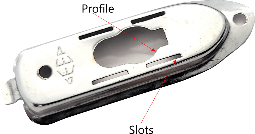
Notching
Notching is fundamentally the same operation as blanking and piercing, the only difference being that notching is performed on the edges (outer contour) of flat blanks.
However, this definition is somewhat inadequate as notching is not limited to flat surfaces only – it is often performed on curved surfaces, too.
Because notching is essentially performed on the edges, notching punches encounter an imbalance of load acting on them. The load imbalance is the result of some portion of the cutting edges of the punch not participating in the notching process. This makes designing notching punches more challenging than blanking and piercing punches.
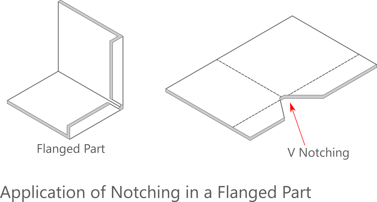
Notching is extensively used before bending and flanging of metal enclosures for electrical and electronic equipment. A variety of geometric shapes are notched out of blanks at strategic locations. Here’s an example of a V-shaped notch commonly used before a bending operation.
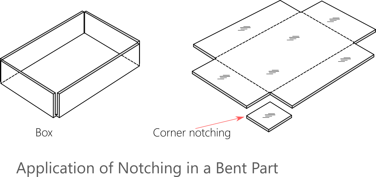
In corner notching, material is removed from the two adjoining edges. This helps in creating a box, as shown below, by bending along four lines.
Notching serves a very unique purpose in progressive dies. Maintaining an accurate and repeatable progression is absolutely necessary for a successful progressive die stamping process. Progression is the distance the stock strip should advance before each hit of the press. In the following Figure 1, progression is represented by ‘P’.
At the outset, the stock strip rests on the die face covering the piercing station and pushing against a stopper as shown. The blanking station doesn’t have any portion of stock strip covering it yet. The press ram is about to descend.
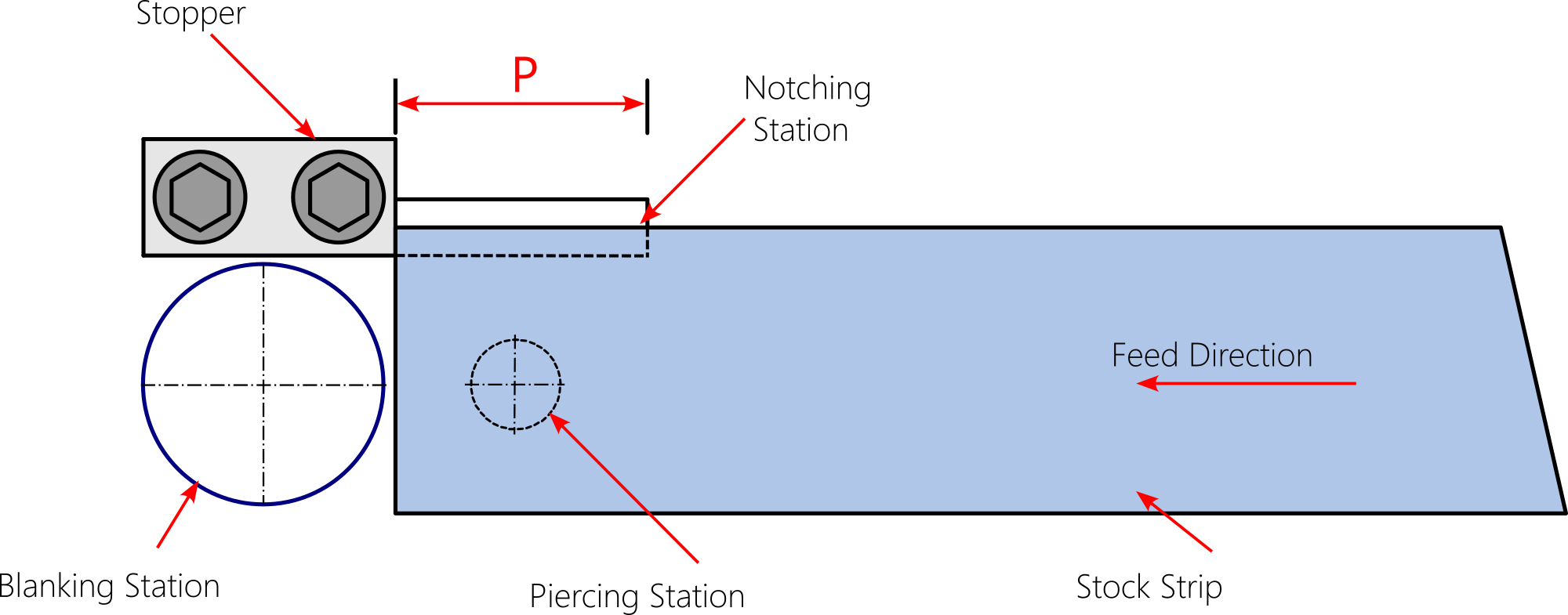
Figure 1
The ram descends, the first hit of the press is accomplished and with that, the first notch is cut and the first hole is pierced. See Figure 2 below. Corner A gets created as a result. Note that because the material is removed at the notching station the stock is no longer constrained by the stopper. The stock strip, when pushed in the feed direction, moves freely until it is stopped by the mating of the stopper corner and notch corner ‘A’.
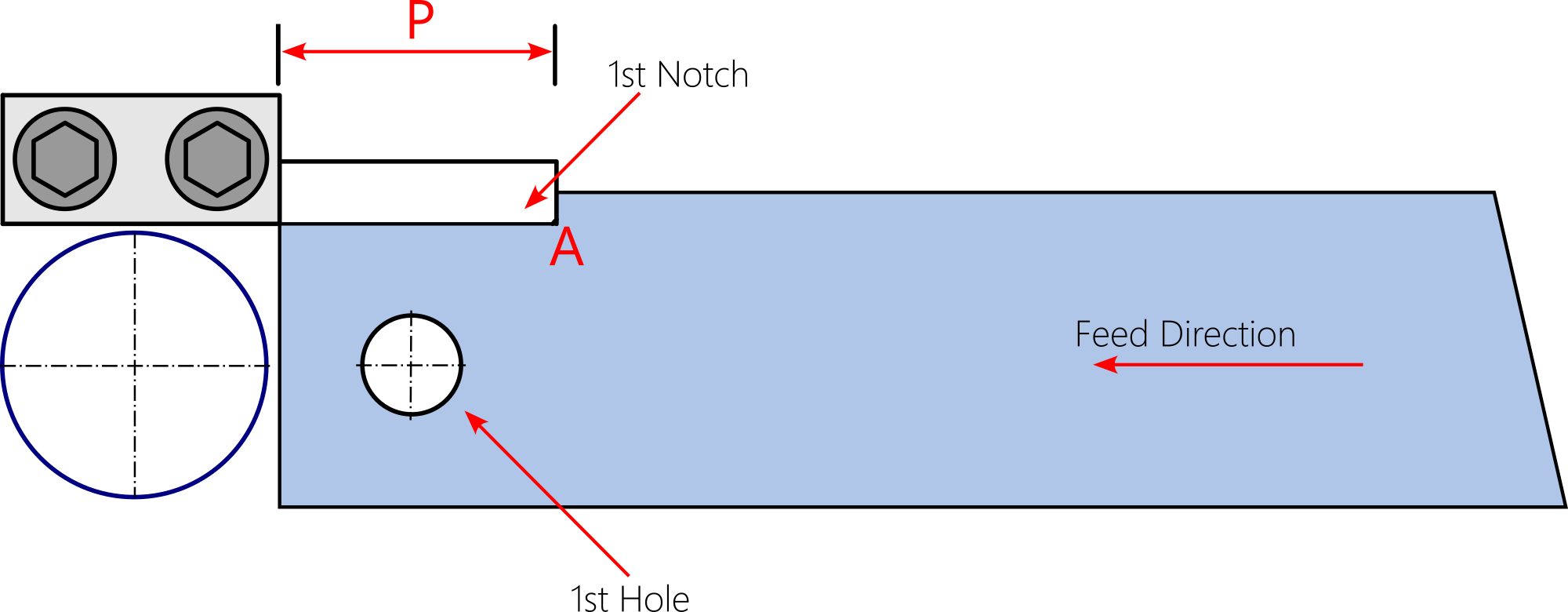
Figure 2
Figure 3 below shows the next stage. The strip is again resting with corner ‘A’ pushing against the stopper after having moved through distance ‘P’. There’s no way it can overshoot this distance. The stopper comes in the way. The first hole has moved – through the same distance ‘P’ – to the blanking station. The press is ready for the second hit.
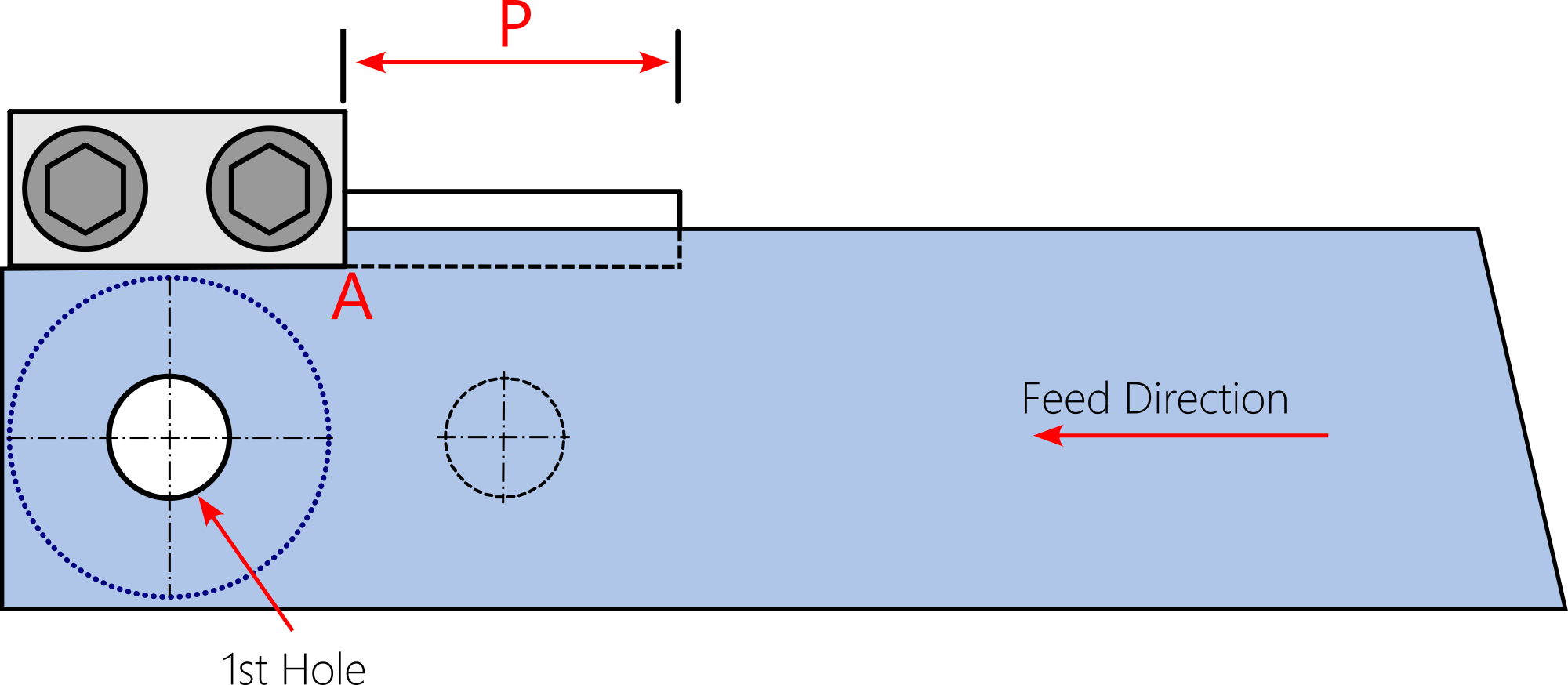
Figure 3
As the press hits the second time, second notch, second piercing and first blanking is accomplished, as shown in the following Figure 4. A finished part , washer in this case, is produced. From now onward, each hit of the press will yield a finished part. This is how notching helps in maintaining a consistent progression.
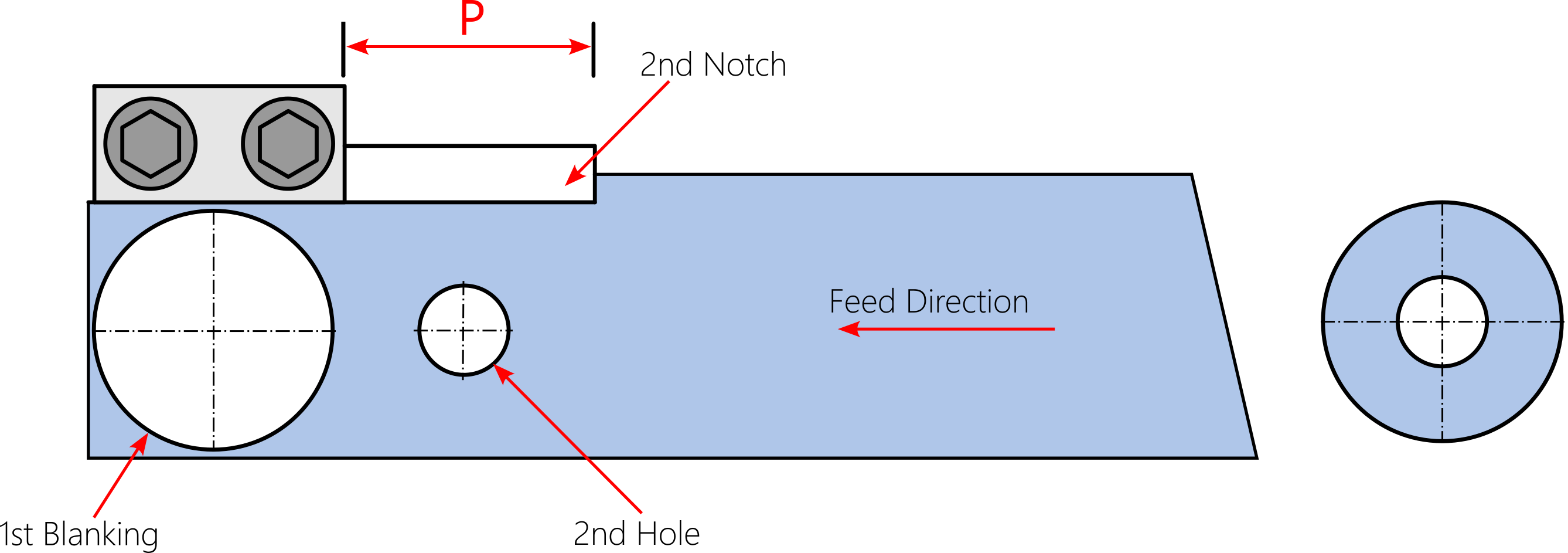
Figure 4
This type of notching is also known as the ‘French notching’ and ‘pitch notching’. The stock strip is required to be wider than that in conventional blanking die as ‘additional’ material is needed for notching operation. For stocks wider than 100 mm (approx 4 in), two French notches placed opposite each other, are recommended

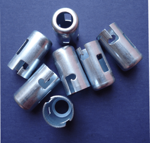
It’s not necessary that the parts to be notched have flat surfaces. Notching is frequently performed on the ends of tubes and pipes before joining them together. A notched end mates to another pipe or tube in a snug manner facilitating a robust welded joint.
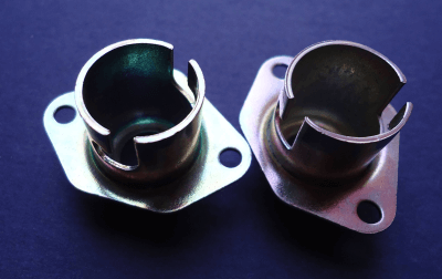
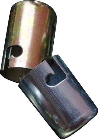
Notching is often performed on curved surfaces of drawn cups and shells to create various features. Shown at the right is an example wherein a previously drawn automotive holder is notched at the lip to create ‘J’ shaped notches that retain the bulb.
Cutting off and Parting
A cutoff operation is one in which a part is separated from the stock strip in a single linear or curvilinear cut.
A parting operation is very similar in objective but the cutting is performed along two straight lines or curves instead of a single line or curve.
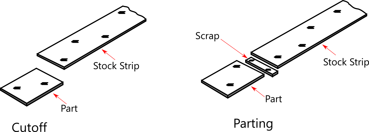
The cutoff operation is very economical as the sides of the stock strip become the sides of the cutoff part. No scrap is generated. If the same part were to be stamped the blanking route, provision for additional raw material represented by ‘A’ as in the following figure, would be required to be added to stock strip width. However, the obvious disadvantage would be that dimension ‘W’ couldn’t be held to a closer tolerance than that of the stock width.

A cutoff operation has an interesting characteristic the parting operation doesn’t have. The following figure makes it clear. The trailing edge of the previous part becomes the leading edge of the next part in the cutoff operation. Used creatively, this characteristic can be used to make fairly complex flat parts rather economically in cases where mill tolerances on stock strip width are acceptable.
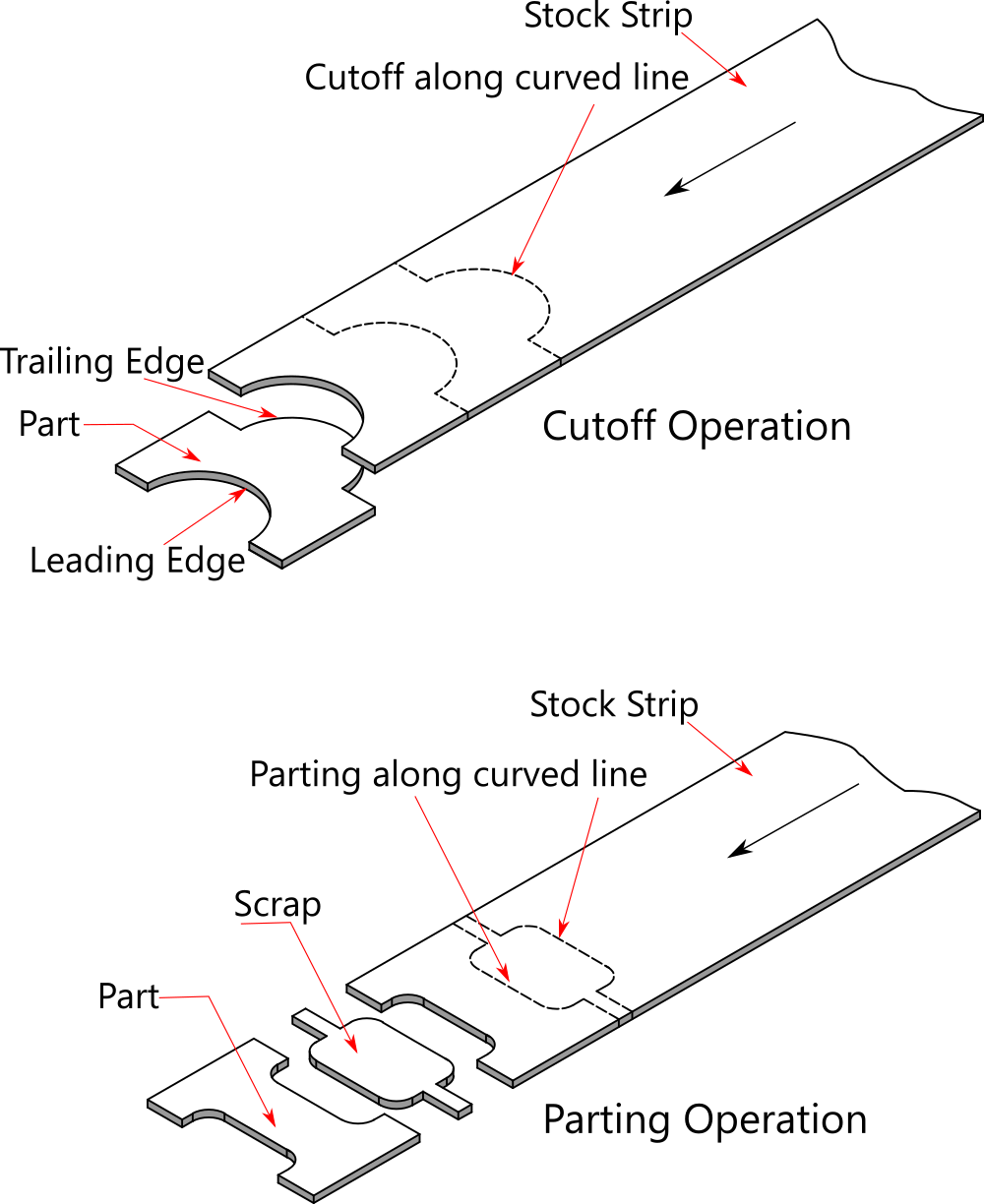
Another notable difference between cutoff and parting operations is visible in the figure above. The cutting punch has only one cutting edge whereas the parting punch has two cutting edges. This is obvious as cutoff occurs along one line and parting occurs along two lines. Also, observe that a cutoff punch cuts the part whereas the parting punch cuts the scrap between adjacent parts.
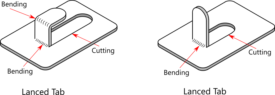
Lancing
This operation combines cutting and bending. The cutting occurs along two or three lines (they may be curves in some cases) and the cut portion is bent along the fourth line. Dedicated punches perform lancing.
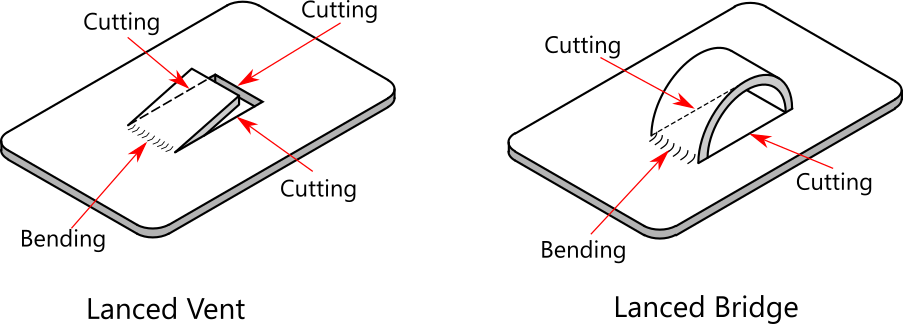
Unlike in other cutting operations, the cut feature remains firmly attached to the part. Lancing is primarily used for creating tabs, vents, louvers, and bridges in the part to serve various purposes.
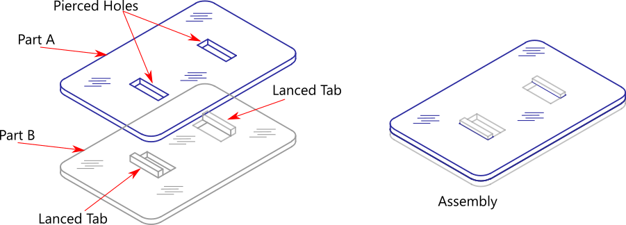
The following figure shows examples of lanced tabs – one featuring two bends and the other featuring one bend. The double bend tabs are used for anchoring other components such as springs. The single bend tab is used for locating another mating component in an assembly.
A lanced bridge version shown in the figure below is used to anchor other components to the part. The lanced bridge differs from other lanced features like tabs and vents in two ways. First, the bridge has only two cutting lines, never three. And second, unlike in vents and tabs, some amount of ‘thinning’ occurs in the bridge. The amount of thinning depends on the height of the bridge.
Sheet metal component assemblies require that parts be located accurately prior to welding, riveting or press-fitting. Lanced tabs are very useful in serving this purpose as shown in the following figure. Part ‘B’ has tabs and ‘A’ has corresponding holes. Tabs engaging with holes locate the parts relative to each other prior to an assembly operation.
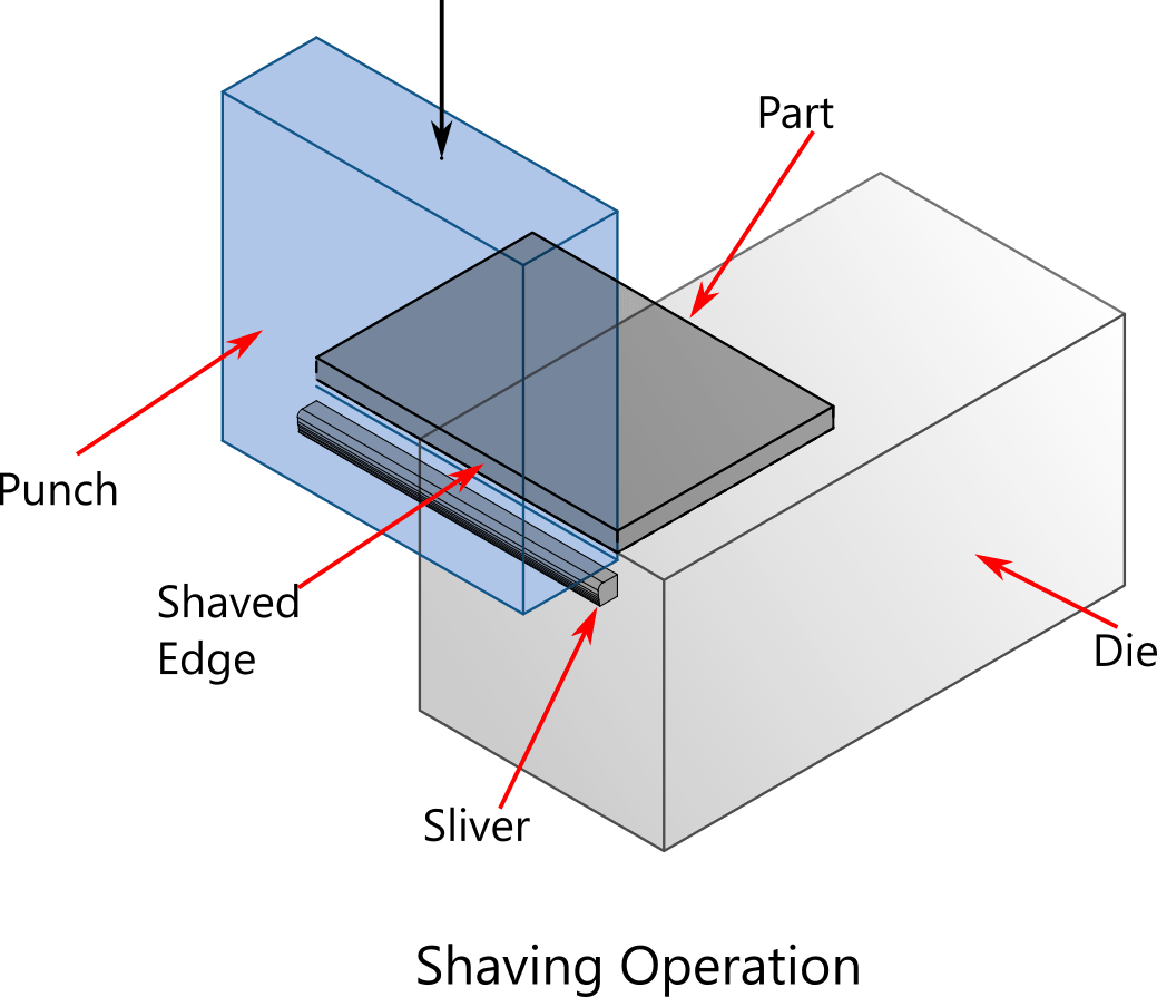
Shaving
Shaving is a cutting operation that removes a minute quantity of material from the edges of previously blanked and pierced parts.
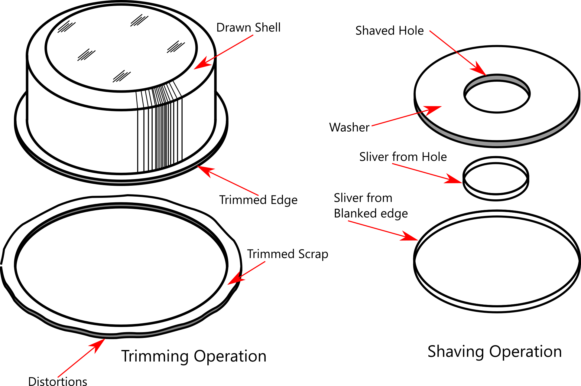
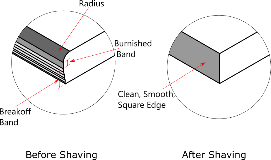
It resembles trimming but differs a lot in its purpose and applications. Trimming is not performed on pierced holes. Trimming is performed on the distorted excess material at the circumference of drawn shells and cups. Trimming creates a normal cutting edge while shaving further cuts away a minute quantity of material from normal edges to improve their quality.
The purpose of a shaving operation is to make previously cut edges clean, smooth, and square. Good edge quality is important in holding part dimensions to accurate tolerances. Such a situation is frequently encountered in stamping high-precision functional parts like sheet metal gears, watch and clock parts, instrument parts, and business machine parts.
Shaving is a secondary operation after blanking or piercing has been performed.
Designing shaving dies requires considerable skill. This is because very little clearance is allowed between punch and die elements.
Extremely small clearances introduce challenges not usually encountered in other types of cutting operations. The slightest lateral movement caused due to misalignment of the die and punch results in nicked or dulled cutting edges.
The orientation of parts (burr side up or down) while feeding them into the shaving die is also important. The determination of extra material (shaving allowance) to be left on blanks or pierced geometries is another significant factor.
Designing locating gauges (known as nests in the US) for shaving dies also needs careful consideration. Moreover, very fine slivers of metal are cut by shaving operation. Leaving them on the die surface, not only poses health hazards but also leads to the poor surface quality of parts and also to impairment of die alignment. Positive removal of slivers is one of the essential prerequisites for a successful shaving operation.
Trimming
Trimming is an operation wherein peripheral portions are cut away from the drawn cups or formed components. This is necessary because, in such components, the farthest portions from the center are often wavy and uneven. The waviness is due to uneven metal flow in drawing and forming operations. Such distortions aren’t acceptable and therefore, they must be removed by the trimming operation.
The following figure shows the most common example of the trimming operation.
The peripheral portions of utensils are trimmed to create a uniform and distortion-free flanges. Round trimming dies are used as most utensils have round shapes. However, this is not the case with a majority of automotive sheet metal stamping.
An accurate determination of flat blank size is a complex exercise. Therefore, only a reasonably accurate blank development is arrived at and a trimming allowance is added to the developed blank size. This is more so in the case of drawing square, rectangular, and other irregular shapes.
The following example illustrates the trimming of a rectangular drawn shell.
Rectangular Drawn Shell
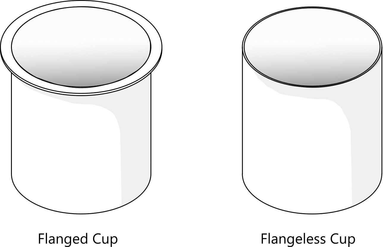
A variation of trimming operation, known as pinch trimming, is used when a flange is not required in the drawn shells.
The edge quality is poor, though. The best edge quality in the flangeless drawn cups is obtained by machining. However, machining is not only as much as 5 times more expensive but also limited to simple round shapes.
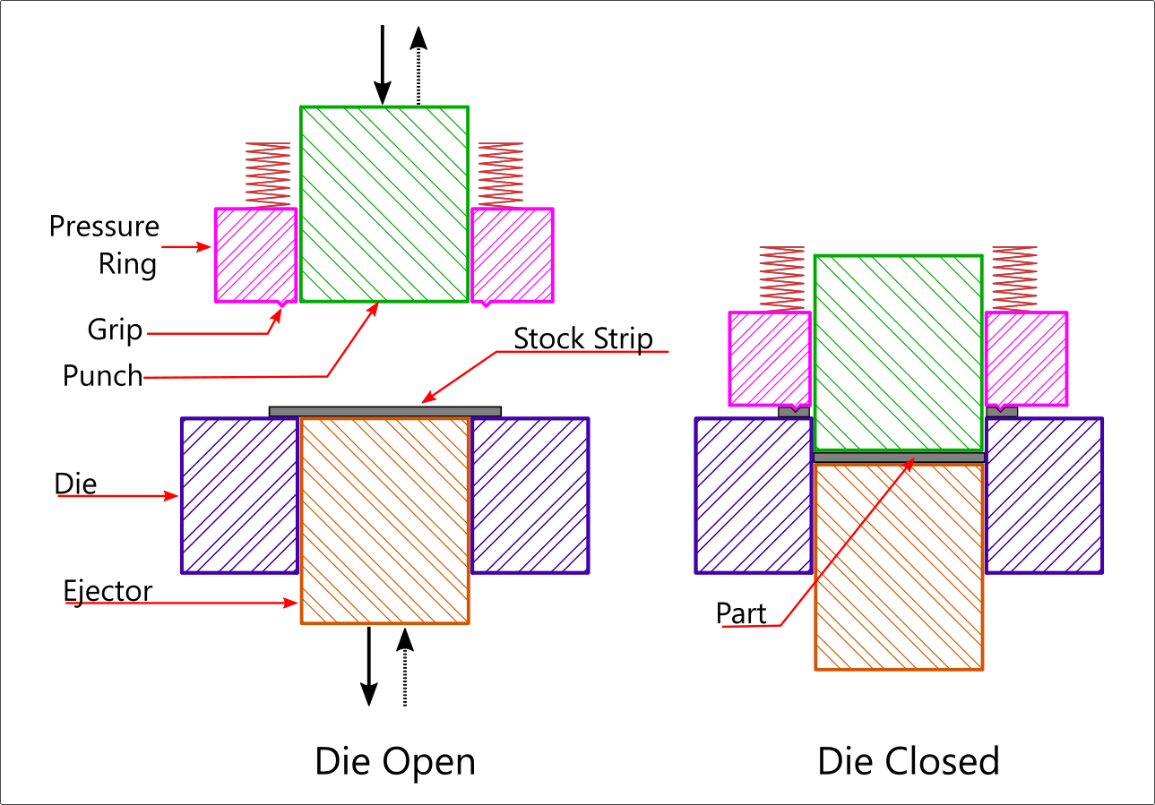
Fine Blanking
Fine blanking is a unique type of blanking which delivers excellent edge quality, improved part flatness, and closely held part tolerances throughout large production volumes regardless of stock thickness.
It differs from conventional blanking in several ways. It employs a special type of pressure ring- often called an impingement ring-that grips and retains the workpiece material very firmly by digging into it a certain depth. It also employs a pressure-assisted ejector in the die opening to apply an upward pressure (counter pressure) which pushes the blanked part up. Clearances applied are much tighter than in conventional blanking.
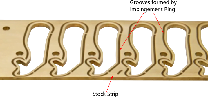
Fine blanked stock strip and part: Image credit: Swiss Tech Precision, Post Falls, Idaho Video
The Fine blanking process is expensive. The fine blanking dies also cost more at approximately 1.5 to 2 times the conventional blanking die. Further, as can be seen from the fine-blanked stock strip picture above, material utilization is comparatively lower leading to higher material cost per piece part. However, the higher investment is justifiable because of the elimination of a secondary finishing operation.
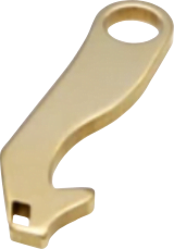
The fine blanking finds extensive applications in the industry sectors such as automotive, aerospace, medical equipment manufacture, and defense equipment manufacture, primarily for the production of parts requiring stringent functional requirements. Such parts include chain links, sheet metal gears, cams, clutch plates, etc.
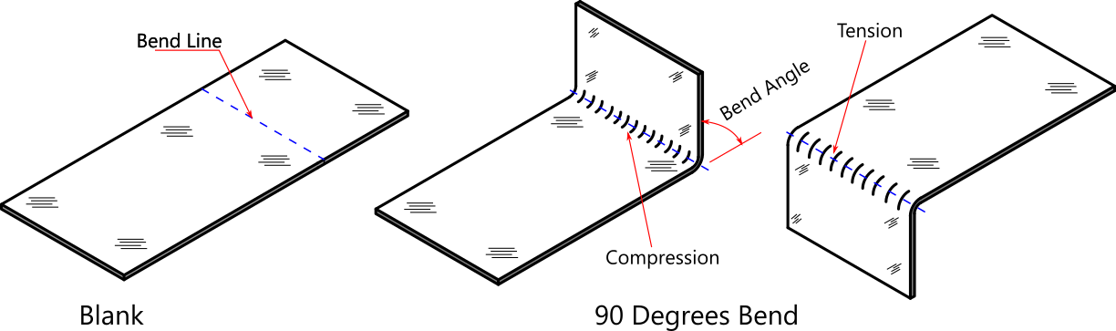
Bending
A bending operation is one in which metal is shaped around a straight line that runs across the material.
Whereas all cutting operations deliver flat parts having only two dimensions, bending operations impart the third dimension by shaping flat parts. Bending operations are a very important group of sheet metal stamping process.
The original plane of the flat blank is divided into two or more planes at angles with the original plane. The bending operation is characterized by a uniform flow of material along the bend line, with the inner surface under compression and the outer under tension.
The following picture illustrates a variety of bends in not only sheet metal but also wire. Note that all bends are along straight lines and that there can be multiple bends in one single component.
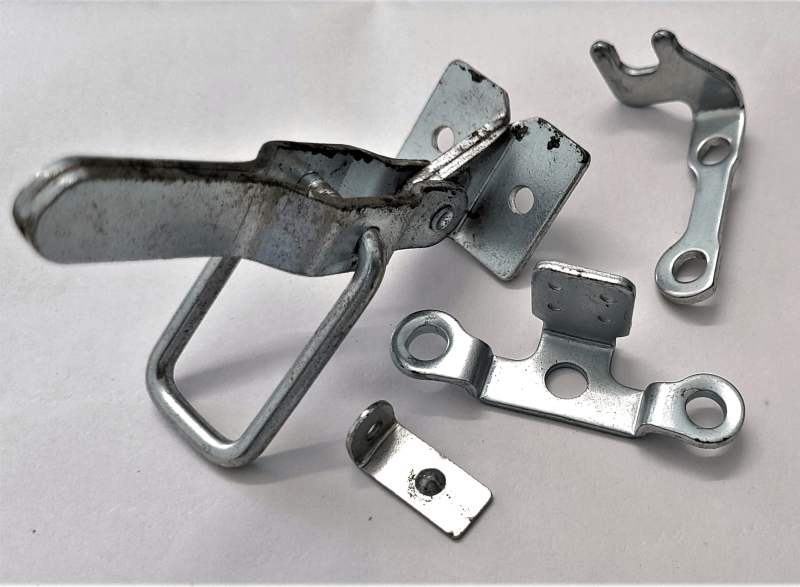
An assortment of bent sheet metal parts
The four main types of bending processes classified on the basis of the resultant shape are namely, L-bending, U-bending, V-bending, and curling. They are shown below.

Most bent components have a combination of these four basic bends. One particularly interesting and distinctly different type of bending process often used for stiffening edges; producing a smooth border, and also for mechanically joining two thinner parts is hemming. Hemming is the process of bending the sheet metal over itself. The joint is called a hemmed joint. The hemming is suitable only for lower thicknesses.

Forming
Forming is essentially bending around a curved line instead of a straight line as in plain bending as shown below.

The most distinguishing feature of the forming process is that the formed part generally takes the shape of the punch or die. Some forms may require a mating punch and die members with allowance between them equal to the stock thickness.
The forming process shapes the metal to the part contour laid down in the print. Additionally, it is employed to reinforce weaker sections of the part; increase rigidity; eliminate sharp edges; add details that help in projection welding; add details that help in locating the part in assemblies; and impart aesthetic appeal to the part.
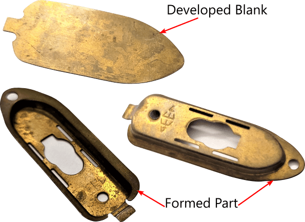
Metal flow in the forming process is usually not as uniform as in bending. Forming operations may be simple or complex requiring a higher level of design skill in developing flat blanks. Illustrated below is a complex formed component and its flat blank that took me five iterations to come within reasonable accuracy. A trimming die was made unnecessary because of the reasonably accurate blank.
The forming process is divided into the following operations. These processes are briefly described below.
- Embossing
- Coining
- Curling
- Bulging
- Restriking
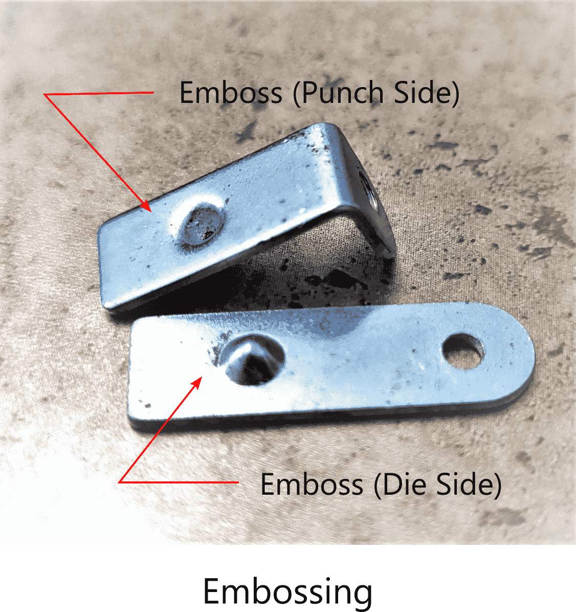
Embossing
The embossing process is a forming process carried out to a shallower depth and over a smaller area. The difference is one of the degrees. Dimples and reinforcement ribs are prime examples of the embossing process.
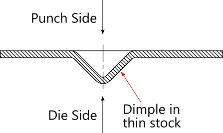
The metal is stretched over a male die member (punch) so it conforms to the shape of the punch. A female die member aids in contour forming by mating with the punch. This is shown in the dimple in the illustration on the left below. Because the dimple is larger than the stock thickness, no alarmingly high thinning occurs at the dimple cross-section. However, in the part shown on the right below, dimples are significantly smaller than the stock thickness, and therefore, a significantly higher degree of thinning occurs. This is shown in the cross-sections below these examples.
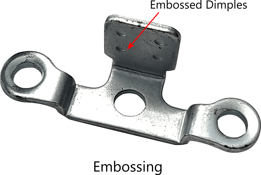

It is uncommon to not find simple circular embossed details or similar contours on utensils and containers. Such embossing increases the rigidity of flat and thin surfaces as shown below.

One other very frequently employed embossed detail in the sheet metal stamping process is the gusset emboss. It is frequently found at the bending lines of bent components such as angles and brackets.
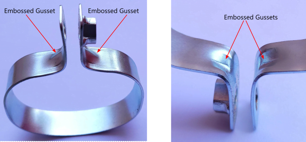
Embossed Gusset Reinforcements on the Bending Line
A concave contour formed at the bottom of all aerosol cans and cans of carbonated drinks is a very common example of strengthening thin containers with embossing.
Coining
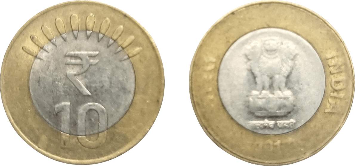
Coining is a type of forming process wherein the metal is squeezed under tremendous pressure so it fills all the space in the die cavity.
Because the metal is forced to flow into crevices in the cavity, all surface details in the die cavity are reproduced on the surface of the part. All currency coins are produced by the coining process.
Terms such as ‘cold forming’ and ‘cold forging’ are often used interchangeably to describe coining. This is because coining resembles very much hot forging with the only difference being that the workpiece is heated in forging.
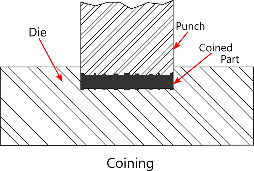
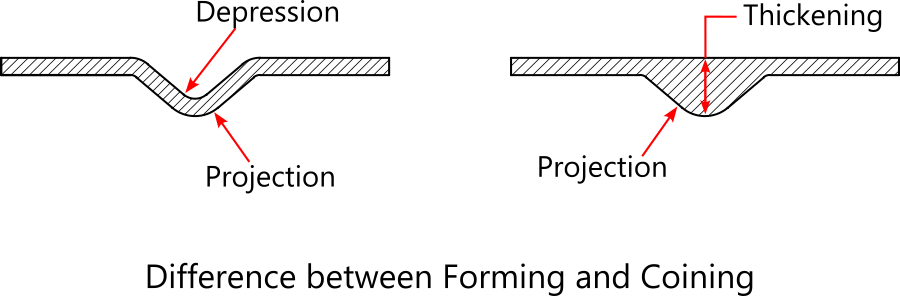
The coining differs from embossing in that the embossed detail is raised on one surface and depressed on the opposite surface while a coined detail can be raised or depressed on both surfaces. Thinning of the stock may occur in forming. With coining some portions may undergo thinning and some portions may undergo thickening.
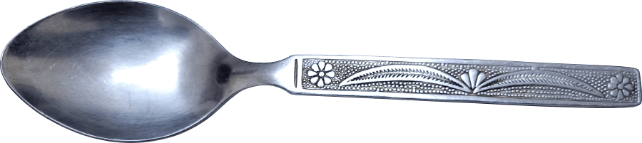
There are two major advantages of the coining process. Minute and complicated decorative details can be reproduced with the exceptional surface finish, and very close tolerances can be held. Cutlery articles like spoons and forks have traditionally sported ornate coined designs on the handle.
Curling
Curling is a forming operation in which the edge of the part is rolled into a curl. This offers protection from the rough and sharp sheared edge; improves the appearance of the part; and stiffens the area surrounding the edge.

Curling is usually found in thin sheet metal products because the smaller thickness is more suitable for rolling over small radii.
It is very common to find curled edges in products that are meant to be handled with hands as in utensils. Curls eliminate the possibility of sharp edges coming in contact while handling. Drawn shells often have curling operations performed at the lip.
Bulging
Bulging is a forming operation in which previously drawn shells are expanded by the application of radiating pressure on the inner surface. However, bulging is not limited to drawn shells only. Pipes and tubes are also expanded outward for functional and aesthetic purposes.

Re-striking
Re-striking is a secondary forming operation in which the bottom radius of a drawn shell is re-struck to reduce it.
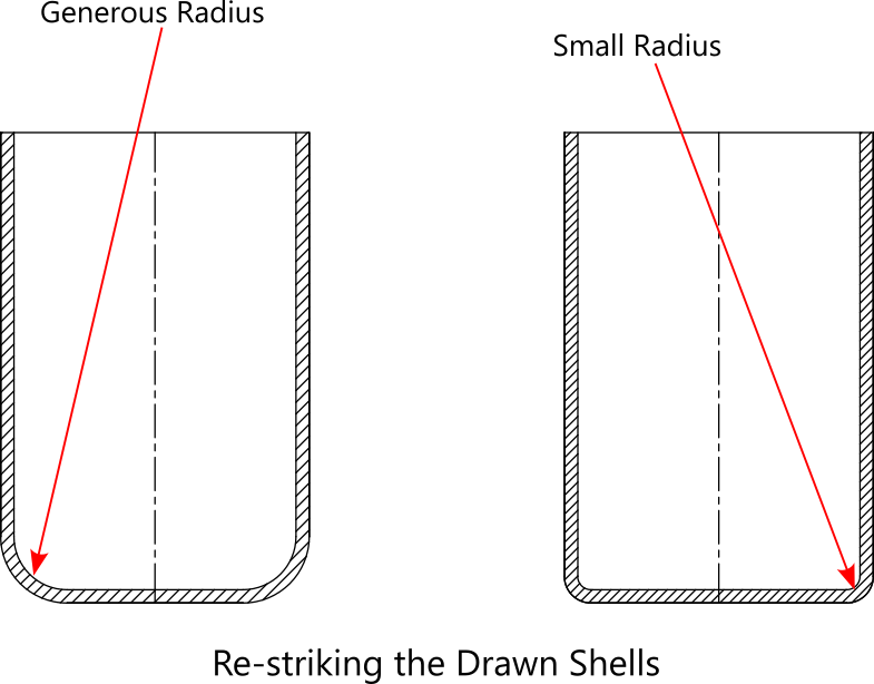
The limitation on the minimum radius at the corner of drawn shells often makes it mandatory to have a generous corner radius. But the part print mentions a smaller radius for functional purposes. Therefore, it becomes necessary to include an additional secondary operation to reduce the radius to conform to the print.
Just as shaving is a secondary finishing operation in blanking and piercing, in the same way re-striking is a secondary finishing operation in the drawing. The part geometry undergoes no significant change except for the reduction of the corner radius. A punch with a smaller radius strikes the radius portion to accomplish reduction.
Smaller radii are unattainable in the primary drawing operation because smaller radii on parts necessitate smaller radii on the punch which leads to tearing during the drawing operation.
Drawing
Drawing is the process in which metal flow is controlled in such a manner that a metal blank is transformed into cups, shells, boxes, containers, and similar articles.
Although the change in the shape is great, the surface area, and therefore, the weight of the drawn part remains the same as that of the blank.
Of all the sheet metal stamping processes, the drawing process presents the biggest challenge to die designers and die-makers alike. Considerable skill and experience is required to accomplish them successfully.
Because of an uneven metal flow in drawing rectangular and other non-circular shapes, they are more difficult to produce than round shapes. A drawing-quality metal is required for drawing operation.
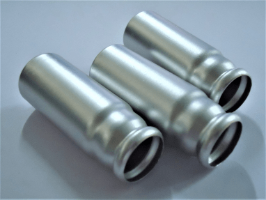
Spray Containers
Automotive Bulb Holders
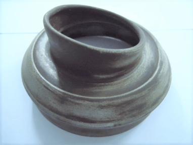
Silencer End Cap
Shown above are some of the drawn parts which I manufactured using dies I designed and built.
The drawing process is further divided into
- Shallow Drawing
- Deep Drawing
- Redrawing
- Ironing
- Collar Drawing
Each of these processes is discussed briefly in the following paragraphs.
Shallow Drawing
A shallow drawing operation, as the name suggests, is a drawing operation in which the article is no deeper than half its diameter. In other words, if the ratio of height to diameter is less than or equal to 0.5, the draw is called a shallow draw. A greater ratio suggests that the draw is a deeper draw and needs several successive drawing operations or passes to conform to the print.

The shallow drawing operation is much easier than deep drawing because of very little likelihood of the occurrence of tearing and wrinkle formation. This is due to less severe plastic deformation of the metal.
Lids of containers are generally shallow drawn whereas containers are most likely deep drawn.
Deep Drawing
A deep drawing operation is a type of drawing operation in which a deeper shell or container is drawn in several successive stages with each stage having a smaller diameter than the preceding stage. The deep drawing process is resorted to when the height to diameter ratio of the shell exceeds 0.5.

In order to understand what the metal goes through during the drawing process, let’s consider a drawn cup shown below. The cup can be considered to have been constructed from a bottom disc (section A), a ring-like 3-dimensional surface (section B), and the larger tubular surface (section C)

Because the drawing operation is so planned as to have very little or no thinning of material, the surface area of the shell equals a total of all the surface areas of individual component sections A, B, and C. These areas look like discs and rings in the flat form as shown. The final circular area so obtained is the blank, the die for which is always built after building the draw dies.
The flat circular blank is placed in an appropriate nest (locator) on the die face. As the press ram descends, the punch forces the blank into the die opening. Except for the flat bottom material, all blank material is drawn into the die opening progressively. The bottom disc material doesn’t undergo any rearrangement of internal structure. However, material at all other sections has to ‘flow’ inward and wrap around the punch by undergoing varying degrees of compression. This compression tends to thicken the material but a binder (also called a blank holder) pressure keeps thickening in check and facilitates an even ‘flow’ of material from the outer periphery of the blank into the die opening. The further away from the central disc, a portion of the blank is, the greater the tendency of the material to fold over itself (wrinkling).
A deep drawn part always has conditions suitable for wrinkling because of the very proportion between its height and diameter. A small diameter relative to a bigger height necessarily translates into a big difference in the diameter of the central disc (bottom of the shell) and that of the blank. There is more material needed to be drawn into the die in order that it wraps around the punch neatly. Therefore, shells with bigger h/d ratios become increasingly difficult to draw in one single pass. The solution is to divide the drawing process into as many draws as warranted by the value of the h/d ratio.
Redrawing
The redrawing operation is a secondary operation in which a previously drawn shell is drawn again in a die with tight clearance so the tapered walls are straightened out.
Successful drawing operation requires that the clearance between the die and punch be slightly greater than the stock thickness at about between 1.05 to 1.15 times the stock thickness. This results in a slight taper as shown below. If the part print warrants a straight wall the redrawing operation becomes necessary.

The drawn shell is redrawn in a separate die with a tight clearance which equals stock thickness or only slightly smaller (0.02 to 0.04 mm)
Redrawing also results in an improved finish on the outer surface of the shell.
Ironing
The ironing is a secondary drawing operation in which a previously drawn shell is drawn again with the intention of reducing its wall thickness. It should be noted that while the outer diameter of the shell is decreased, the inner diameter and the bottom thickness remain unaltered.

The shell is redrawn in a die with a smaller diameter. The walls get squeezed to a uniform predetermined thickness. This results in a slight increase in the height of the shell.
There are instances when the outer and inner diameters must conform to part print. Plain primary drawing operation cannot deliver such a high degree of conformity to dimensions. Ironing is resorted to in such instances.
Besides imparting exacting dimensions, the ironing operation also helps in improving the finish on the outer surface of the shell.
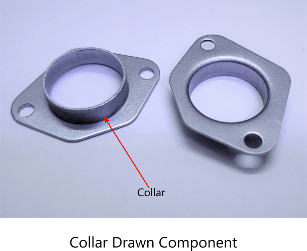
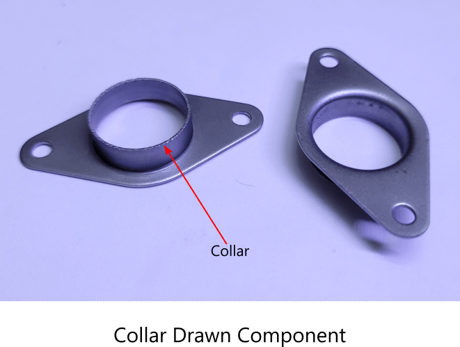
Collar Drawing
The collar drawing, as the name implies, is an operation in which material around a previously pierced hole is drawn outward to form a collar.
The important distinction is that unlike in the drawing operation, here material is drawn away from the center of the part. A hole is necessary for collar drawing operation.
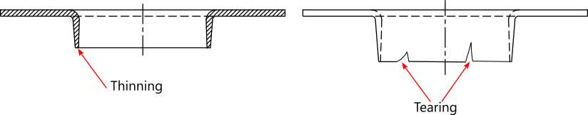
The amount of thinning increases in direct proportion to the increase in collar height. A limiting height is reached when no additional increase in the height can be obtained without tearing of the collar.
A notable distinction is that when the material is drawn outward from the center, the material is under tension which might lead to tearing at the circular edge. This is unlike in drawing inward from the periphery to the center wherein compression results in an increased tendency to thickening. Therefore, the collar section always has a progressively decreasing thickness as shown below.
Shown below are two components with collars drawn around holes. The stock thickness was 0.8 mm in both cases. The thickness observed at the deepest points was between 0.5 to 0.6 mm. Attempts to increase the depth of draw from 5.0 mm to 6.0 mm resulted in tearing due to excessive thinning as shown in the figure on the right below.
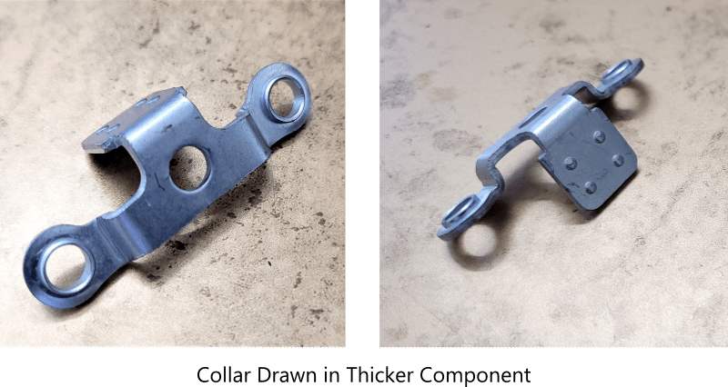
What is the purpose of collar drawing? Collars are drawn for assembly purposes. Collars are folded onto themselves in riveting operations like in eyelets. In thicker parts, collars are often drawn so threads can be cut on the inner surface for assembly purposes. Sometimes another part is just press-fit into the collar.
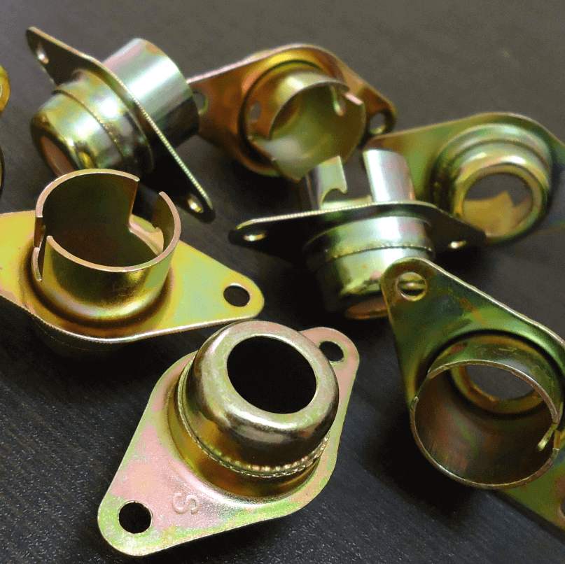
Press fit assemblies using drawn collar
What are the disadvantages of the sheet metal stamping process?
Like every other manufacturing process, the sheet metal stamping process has its limitations, too.
The major disadvantages are as follows:
- Many applications require parts with a variable thickness for increased strength. Stamping cannot be produced reliably and repeatably with varying thicknesses.
- Very small radii and angles are not possible to obtain in case of bending of thicker sheet metal stamping.
- Smooth, rounded, and square edges are not obtainable in the stamping process.
- Very small and very large stamping are impractical to make via the stamping process.
- Stamping works best with soft and ductile sheet metals, and this property is not helpful when it comes to strength.
- Presses are very expensive. So are the dies.
- Dies are unalterable to accommodate slight modifications in part designs.
- Dies require a comparatively longer development time.
- The sheet metal stamping process isn’t an economical choice for small-volume production.
Conclusion
The sheet metal stamping process is a manufacturing industry workhorse. Stamping finds applications in all walks of life. It is the preferred metalworking process when huge production volumes, repeatable precision, and lower part costs are the primary goals. Therefore, the stamping process is employed extensively in the automotive industry. The stamping process has its own limitations, though.
FAQs
What factors determine the number of steps required to stamp a sheet metal part?
The most important factor is part geometry. Other determinants are part tolerances, edge quality, and the application environment of the stamped part.
What factors determine the process cost of stamping?
The two biggest factors are stock strip layout and the number of steps required. Ideas are explored to optimize the former and minimize the latter.
For a simple two-step part, it is the layout that will override other considerations. Conversely, minimizing the number of steps will be the main consideration in case of a complex multi-operation part.
The third important factor is the production volume, as a bigger production volume drives down the cost significantly.
How is more than one cutting operation accomplished in the sheet metal stamping process?
More than one distinct operation can be accomplished in a stamping die. Two cutting operations , namely blanking and piercing, are combined in what is known as a compound die. Likewise, a cutting and forming operation can be combined in a combination die.
A progressive die can combine many operations such as piercing, bending, forming, shallow drawing, deep drawing, trimming, etc. The multi-operation dies are built to accomplish many operations for each stroke of the stamping press.
Why is blanking the first step in the sheet metal stamping process?
The stamping are made from metal sheets or coils. In most instances parts have more than one operation. It is more convenient from the part handling perspective that blanks be first cut from the sheets and coils, and then fed to the dies for subsequent operations. Having blanking as the first operation in the series, therefore is more convenient.
A notable exception, though is the progressive die stamping process in which metal coil is automatically fed to the die and the blanking operation carried out at the last station separates the finished part from the coil.
Quiz on stamping process
This is a quiz to test your understanding of the stamping process.