How these slender piercing punches were designed-A case study
Do you know what is the weakest link in a piercing die?
It is the punch or punches, if there are several of them. It is the most vulnerable die part. More so when the hole to be pierced is very small.
The piercing punch is always the same size as the hole. Therefore, for smaller holes the punches are be smaller in diameter (if it’s a round hole). The small diameter punches are more susceptible to breakage due to buckling.
In this case study, I am going to discuss in detail how I got around the problem of designing slender punches in a piercing die.
The problem: these slender piercing punches wouldn’t work
The part in question is shown below in Fig.1. It was a part of switch assembly for the torch light. The material was brass and the sheet thickness was 0.45 mm (26 gauge, 0.018″).
The 4 narrow windows each 0.9 mm wide and 11.5 mm long (0.036″ x 7/16″) were to be pierced. Other pierced features were a breeze so I am not going to dwell on them. However, I had had an inkling right at the beginning, that the narrow windows were going to present problems in the piercing operation because they would involve slender piercing punches.
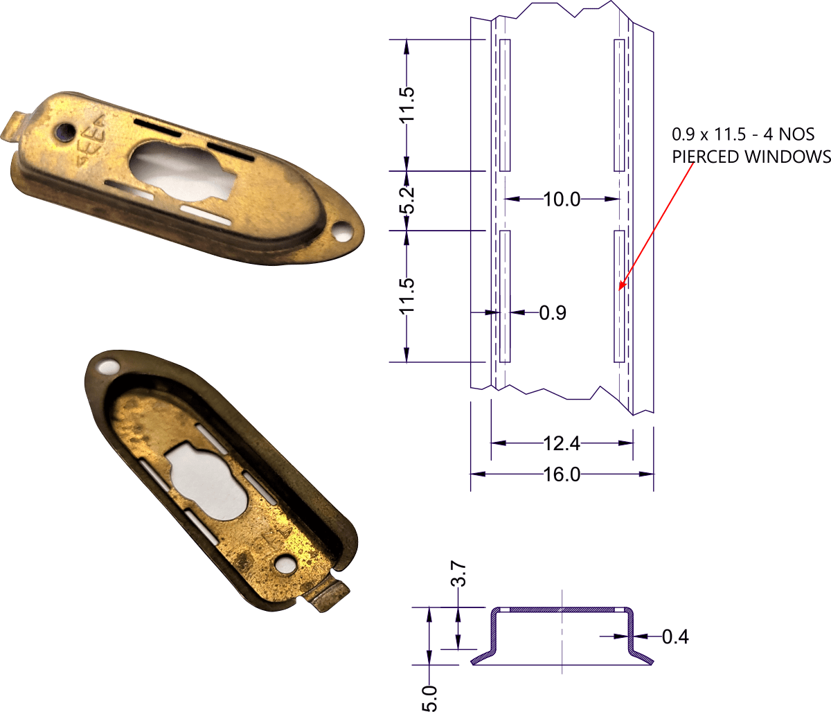
Fig.1
Because of the anticipation of this potential problem, I decided to make the punch plate only after the piercing punches were made. I kept the tentative design of the punch plate ready, though as shown below in Fig.2 and 3.

Fig.2
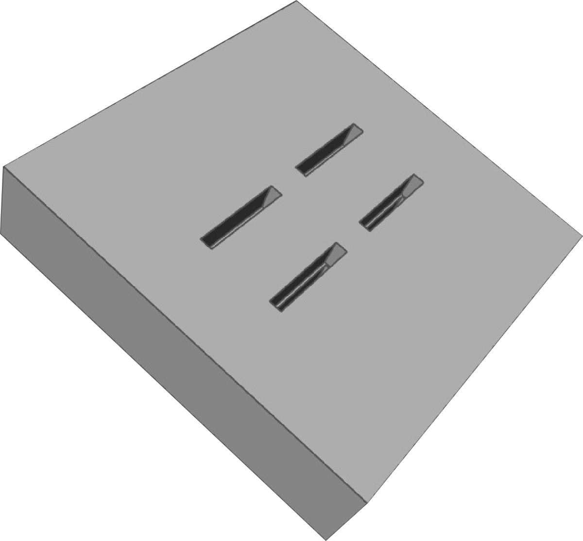
Fig.3
The first ideas you get when faced with any problem are often the most obvious ones. Obvious ones have proved their utility in the past and therefore they kind of become the standard solutions. Why would anyone want to look for fresh new ideas ? The obvious , time-tested ideas were:
- making them by grinding to the required size
- cutting them from a hardened tool steel block by wire EDM process
The shape of the punch was a regular geometry. Such punches have traditionally been made by grinding because wire EDM process wasn’t invented back then.
Even for a long time after EDM became the preferred process for making punches, people with exceptional grinding skills were still around.
Grinding works out to be way cheaper than the wire EDM. So I decided to try it.
But it failed miserably. The piece of hardened tool steel would become very hot and warpage would set in. This wasn’t going to work, I realized.

Fig.4
The second option would require peening one of the ends to form a ‘head’ as shown in Fig. 4 above. The head helps retain the punch in the punch plate.
However, slender and fragile punches would lose its flatness due to peening.
The solution: redesigning slender piercing punches
Knowing what wouldn’t work was helpful because it opened up a new direction for exploration. I explored some ideas shown below in Fig.5. This helped me form a somewhat vague idea about what might work.
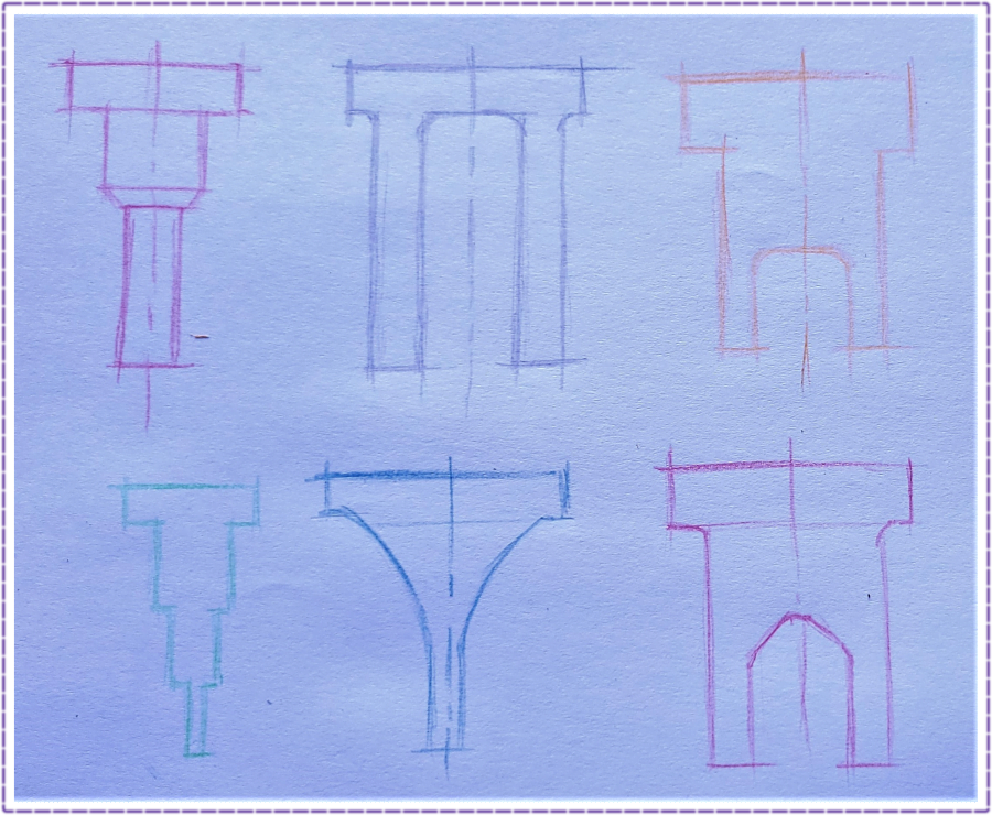
Fig.5
The salient points that became apparent were:
- The punches need not be fragile and slender all over. Just the portion that would participate in the cutting must be the size and shape of the windows.
- The corresponding geometry for retaining punches in the punch plate could be a bit complex as a trade-off.
- The punches could be combined so they had more mass and therefore higher rigidity. This would make them stronger and solid. As a result, the punches would be easier to handle, hold and grind.
The punch design
The final punch geometry that was compellingly inviting is shown below in Fig.6a and 6b.
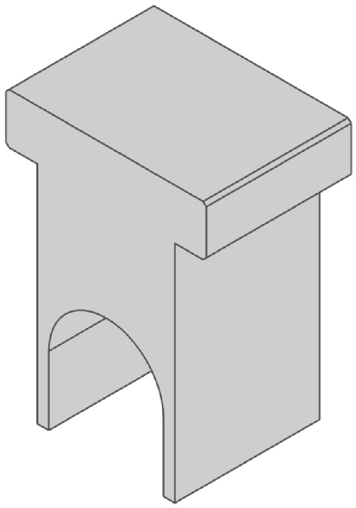
Fig.6a
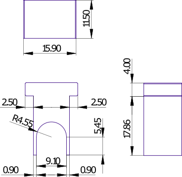
Fig. 6b
A small block of tool steel (WPS) was machined, ground and hardened. A grinding allowance of 0.7 mm (0.35 mm per side) or 1/64″ per side was left on the thickness of the block. Post heat treatment, this allowance was ground away to have block thickness the same as the punch dimension 11.5 mm (7/16″). This was done with the purpose of doing away with grinding of the tiny punches post wire EDM process. The punches were then cut from this block by wire EDM as shown below in Figures 7 and 8.
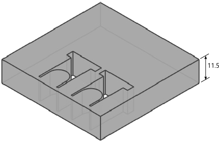
Fig.7
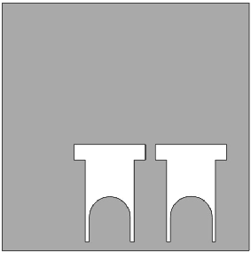
Fig.8
The result was exceedingly fulfilling!
Design of the punch plate
Now I turned to the design of the punch plate with renewed vigor. The previously made tentative design was discarded. It was a no brainer to figure out the punch plate design now that I had the punches.
The punch plate was designed to have ‘stepped’ pockets as shown below in Fig.9
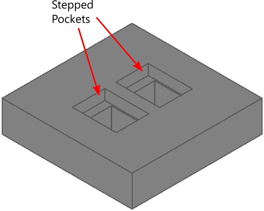
Fig.9
The EN-31 steel punch plate was machined, ground, heat treated and reground before making those stepped pockets.
The stepped pockets were made by first EDM wire cutting the rectangular openings and then EDM spark erosion machining the bigger rectangular ‘cavities’ to the required depth. A copper electrode was made for this purpose.
The steps in the pockets served the purpose of arresting the movement of punches beyond a certain depth when the punches were driven gently with hammer into the pockets as shown in the following Fig. 10
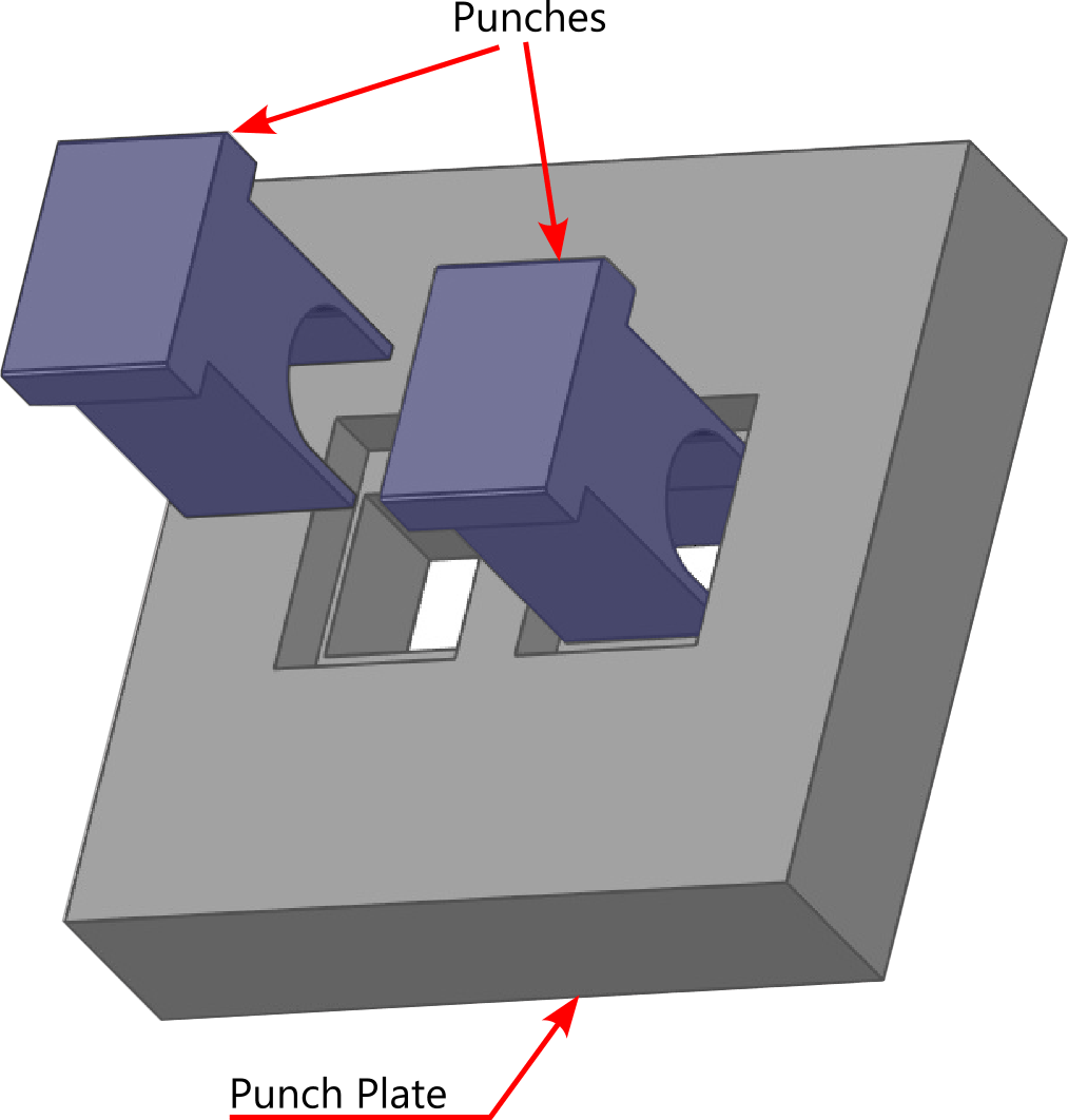
Fig. 10
The punches came flush with the top surface of the punch plate, as shown in the following assembly in Fig. 11
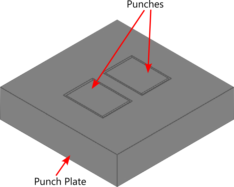
Fig. 11
The assembly, when looked from the opposite side, namely the bottom side, is shown in the following Fig. 12
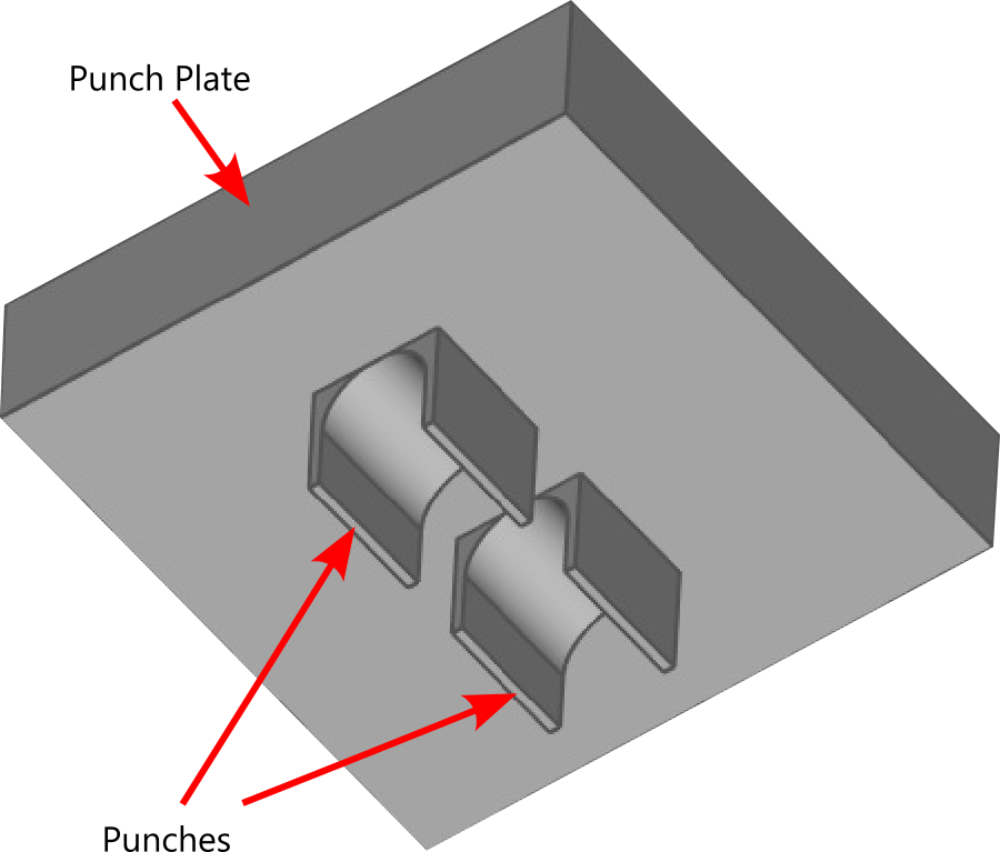
Fig. 12
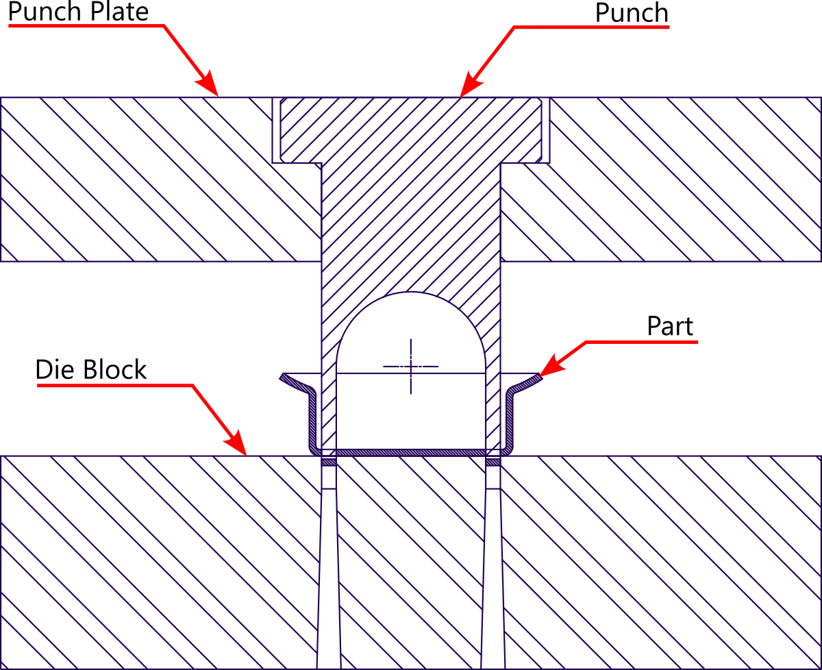
Fig. 13 : Assembly
The result
The tool worked better than anticipated. The results were very satisfying. Grinding blunt punch edges was also very convenient as it did not involve removing individual tiny punches.
Some afterthoughts
As I look back at that experience, some thoughts come up and they are as follows:
1. Will this design work for thicker materials?
No. This design will work better for thin sheet stock. As the stock thickness increases the probability of punch breakage increases. The limiting sheet thickness will be 0.9 mm in this case because then the smallest dimension of the cutting geometry of punch 0.9 mm will equal the sheet thickness. Above sheet thickness of 0.9 mm, there’s going to be a remarkable increase in the incidence of punch breakage at two places in the punch: one at the corner at punch shoulder and the other, anyplace in the fragile cutting portion that projects out from the punch plate.
Stamping part designers are advised against specifying pierced hole diameters (or widths) equal to or larger than the sheet thickness.
2. This design worked because there were even number of punches. A pair of punches was combined to form one single punch. That gave it the necessary rigidity and strength. What if there were just one punch or three punches?
The punch in this case study was made stronger by combining it with another punch. However, the principle involved was this: keep the cutting section of the punch as short as possible and strengthen the rest of the punch body by adding extra material. This principle will give singular punch geometries as shown below in Fig. 14
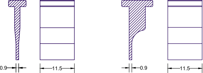
Fig. 14 : Alternative designs for slender punches
3. What if the slender punches were round or square?
In such cases, make the punches as short as possible. This reduces buckling under load. Also have as much length of the punch supported as possible..
Conclusion
Since punches are the most vulnerable part of any stamping die, they should be designed for maximum strength. Additionally, they should be supported for the most part of their length.
Two factors contribute toward high-performance punches, first rigidity and second the method of supporting them. The long and slender punches are even more challenging from the standpoint of designing and making them.
In most instances, trade-offs become necessary. These trade-offs are likely to be a more complex design of punch plate, shorter punches, more elaborate punch support and fewer opportunities for sharpening. These tradeoffs translate into relatively higher tool cost and shorter punch life. But the upside is that the tool performs without interruptions unlike in piercing tools with vulnerable punches that frequently fail under buckling.
FAQs
What is a piercing operation in sheet metal stamping?
Many stamped metal parts require holes, cutouts, and openings for functional (sometimes for aesthetic) purposes. The operation that cuts material to produce such holes is known as piercing.
What is a piercing punch in piercing dies?
In a metal stamping die, any ‘male’ member of the die is called a punch. Punch is usually found in the upper die assembly. In most cases it projects out from its ‘retaining’ member.
What is a wire EDM process?
EDM stands for Electric Discharge Machining. In wire EDM process, metal is cut and removed by heat generated from the electric sparks generated between the workpiece and the thin single strand conducting wire. The wire, usually 0.3 mm in diameter is continuously fed through a hole in the workpiece. A program ensures that the wire follows the cutting path. When the cutting path is completed the metal portion is completely cut away from the parent metal plate or block. It’s a slow and expensive process.
What is a punch plate in a die?
In a sheet metal stamping die, there can be one or more punches. The punches perform cutting operations as in blanking, piercing and trimming. But they can also perform forming and drawing operations. Regardless of their intended operation, they are fitted in die members called ‘punch plates’. Thus punch plates are die members that ‘hold’ and ‘retain’ punches. therefore, they are sometimes also known as ‘punch holders’ .
What is buckling of the punches?
The long slender punches are prone to bow outward at the center of their lengths under heavy compressive loads. You are driving a nail into a concrete floor and the nail ‘buckles’ (bends). In the same way slender punches buckle. The longer the punches the more they are prone to buckling.